 Photography
Ring light 4.1: fiber optic TTL ring flash
Note from the author: my ring light pages have had hundreds of thousands of visits since I started writing them back in 2005. Fuzzcraft has been stampeded by StumbleUpon, has starred on Hackaday and DIYphotography, and is constantly being linked to from flickr, strobist and other blogs, forums, etc. I thank you all. It's nice to have done something that appeals to so many people.
There's something magical about ringlights. The unnatural light cast, the halo shadows. Yet the idea behind them is as clever as it is simple: looking through the light source.
Overview
Want to see more ring lights? See my full ring light overview page
Quick overview:
  |
4.1 |
Fiber optic TTL flash ring light, uses popup flash and 67 fiberglass bundles |
  |
4.0 |
Fiber optic TTL flash ring light, uses popup flash and 120 plastic fibers |
  |
3.1 |
2 CCFL continuous ring light |
  |
3.0 |
4 CCFL continuous ring light |
  |
2.1 |
52 mm filter mount 140 LED continuous ring light |
  |
2.0 |
52 mm filter mount 90 LED continuous ring light |
  |
1.0 |
Simple, 30 LED continuous ring light |
The ideas for cheap ring flashes keep coming. This is my 7th approach: a large pre-made bundle of jacketed super fine strands. I ran into an extremely economic deal for professional quality optical fiber assemblies. On one end, there's a ready-made optical connector with all the strands perfectly flat, polished and aligned in a 9 mm diameter window. Then it spreads out into 67 very flexible, jacketed optic wires, which in turn end in perfectly precut ends. Each end has at least 250 single optic fibers, so a crude estimate would be a total of 20,000 fiber strands, but I wouldn't be surprised if there were 50,000. These are actual glass filaments, as I've never seen acrylic fibers this thin. These bundles are made for high visibility electronic traffic signs, and are to be looked at from up to a few hundred meters. Because of that, every end cap has an acrylic lens on it, focusing the light into a very narrow beam. I got these two from a dump shop for €10 each, which is a bargain, because I've seen this kind of optical arrays for hundreds of Euros. I checked recently and they ran out, so that would make it pretty much impossible to get the same awesome deal I got. In case they should ever restock them, here a link to the shop: Baco Army Goods.
F.A.Q.
Question: what's so special about this fiber assembly thing? The 120 fiber ring flash was doing a great job, wasn't it? Well, yes. But it wasn't without one serious drawback: the fit. The plastic fiber is way too stiff to be practical. The ring I built can only be used with one lens I own, a 17-70 mm zoom, but only at 70 mm. What's more, it can only be used on a Konica Minolta Dynax 5D, but later I got a Sony Alpha 700, which is a bit larger, so the flash head mount doesn't work on both of them.
Question: WHY? Well, at this point in time, I'm not doing it to be cheap anymore. My budget for photo gear has risen a lot in the past two years, and I could easily afford a real ring flash. But where would be the fun in that?  Besides, spending it on a lens would actually make a lot more sense, because a lens gets a lot more actual use than a macro-only flash. Spending it on a normal portable flash makes the most sense, so this fiber optic ring can still make a pretty decent, well-performing, if somewhat clumsy, but dirt cheap, TTL ring flash. I actually purchased a Metz Mecablitz 58 AF-1 flash gun recently.
Question: why are you using the internal flash for this, even though you have a much more powerful flash gun in your bag? Well, portability is an important factor, and adding a portable flashgun to this already involved setup would make it close to impossible to handle. Besides, light transmission with optic fiber is very effective, so the popup flash, even at relatively low power, is powerful enough to shoot macros at f/22, which is the limit for most lenses to get sharp images versus good depth of field.
Construction
But let's not go off topic too much. On to the step-by-steps!
Click thumbnails to zoom in. Click again to zoom out, or use cursor keys to walk through all images.

1. This is how the goods arrived. I ordered 2 assemblies.

2. The very heavy and oversized input connector. The business end is 9 mm across.

3. Close-up of the end caps, a flashlight shining into them.
I ran a test, and concluded that, with the acrylic lenses attached, the beam spread was around 6 degrees, which is too narrow for my purpose. So...

4. ...I took out the hot air gun, and removed all 67 lens caps on one of the two bundles, exposing the brass ferrules used to hold the fibers together. Now the beam spread is a lot wider and the fibers can be spaced closer together, making the ring smaller and more portable. Some fiber strands were damaged in the process, but nothing serious. They all still light up brightly.
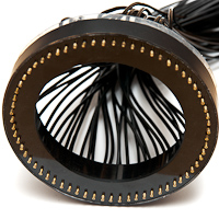
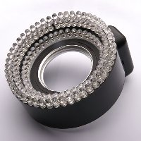
5. I cut a 12 cm plastic disk and marked 67 points around its perimeter, after which 2 mm holes were drilled. The white stuff you see is what is left of the paper template I printed out and glued onto the disk.

6. The disk got a rear extension tube to fit the filter mount I made for ringlight 4.0.

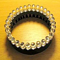
7. And this is the contraption I ended up with. Here, I just used some hot melt glue to put all the ferrules in place. I will have to think up something more durable.
Some quick test shots. For these shots I just held the fiber connector about 1 cm from the flash window of the internal flash of my Sony α700. EXIF: 70 mm, f/8, 1/125, ISO200

8. Notice there's no distinct sharp shadow you always get with direct flash.

9. Exposure is spot on. Except picking the aperture, I didn't do any sort of adjustment. No exposure compensation or flash compensation.

10. In this shot you can see the ring was not evenly lit, as there are sharp shadow lines to the lower left of the subject. It's probably because I held the fiber connector up against the flash (which I did, BTW).
Now how to get the light from the flash tube to enter the 9 mm window on the connector end? I took a strip of aluminium (actually a front panel for a 1 unit high 19" case). I bent it into a U-shaped bracket that starts at the tripod mount and ends just above the flash head. Left and right to the flash head I mounted two steel strips, to which a small plastic plate was attached. In the plastic plate I dremeled a rounded slot for the fiber connector.

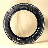
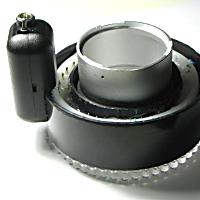
11. This is how the filter mount attaches to the lens. I had to use a couple of step rings. For a description of the filter mount, please see ring light version 4.0

12. The U bracket, made from a 19" front panel, with the two drilled and threaded steel strips.

13. To improve fit and to protect the camera body, I stuck a foam pad onto the bracket.

14. The plastic plate, dremeled into a fiber connector receptacle.

15. The fiber connector has an indent around the front, so it sits in the receptacle almost perfectly. I might have to find a way to actually lock the fiber head into place. We'll see.
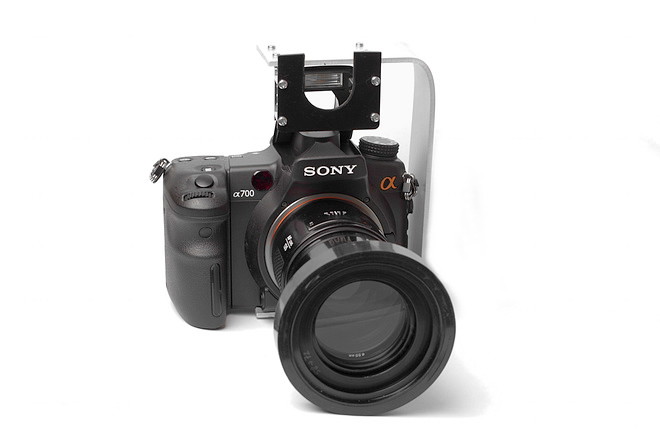
16. The bracket mounted onto the camera (or is the camera mounted inside the bracket?)

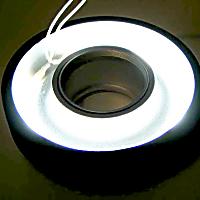
17. The fiber connector in place, right in front of the popup flash window. I need to improve this, because the fiber connector isn't lit evenly. See step 21. Maybe some very small mirrored barn doors or something.

18. Aonther shot of how the fiber connector sits in front of the flash. Nothing actually touches the flash head, so there's no - as in zero - stress on the popup mechanism. This was a major gripe with version 4.0
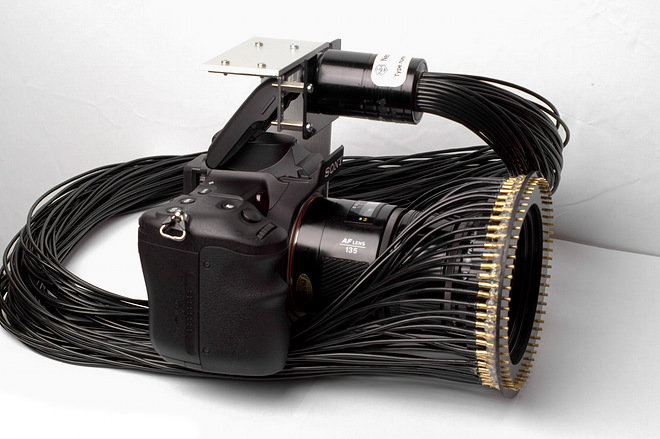
19. This is the setup used for steps 24-29.

20. Front view of the test setup.
You must be thinking: "Gee, that looks cumbersome, a big dangling bunch of wires." And I'd have to admit you're right. Version 4.0 was much easier to walk around with, even easier than a real macro ring flash with the flash tubes around the lens. Then again, who said I ever wanted perfect handling? With this setup, I can use any lens up to a rediculous length of about 80 cm. Who knows, a long tele with extension tubes and a reversed lens up front might come close
Testing, testing...
Well, the proof is in the pudding, right? Let's do a round of test shots with the preliminary setup, as seen in steps 19 and 20.

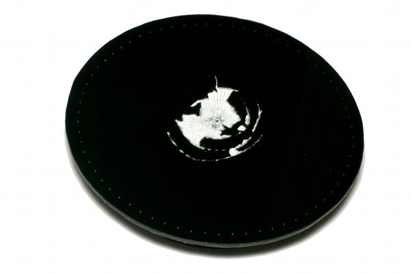
21. ISO 200, 70mm, f/25. A test shot in a mirror to see if all fibers are equally bright. As you can see, there's still work to be done. You can also see the diffraction effects of the very small aperture I picked.

22. ISO 200, 70mm, f/8. The back of one of my studio monolights.

23. ISO 200, 35mm, f/8. My usual cute model. Note the ring light signature catch light. And an all-new experience for me: I can zoom out now!
The following series was shot with a Minolta 135 mm f/2.8 lens at f/16 and 2 Sigma achromatic +1.6 diopters, coincidently giving a 1:1 reproduction ratio with a recorded view of 36x24 mm. But since it was shot on an APS-C sensor it's actually 1.5:1, but that's another discussion. These are all unedited shots, shot in RAW format and converted to JPG with no additional processing whatsoever.

24. ISO 200, 135mm, f/16. Close-up of the test button on the monolight from step 22. Note the circular reflections.

25. ISO 200, 135mm, f/16. Super glue bottle. Please note the image is much sharper than the printed white text.

26. ISO 200, 135mm, f/16. Micro SD adapter.

27. ISO 200, 135mm, f/16. Tip of a Lenspen. Yes, I noticed. I have some dust on my sensor.

28. ISO 200, 135mm, f/16. Wrist strap loop.

29. ISO 200, 135mm, f/16. A700 hot shoe cap.
More test shots
For these and more test shots see the Fuzzphoto.eu Ring light 4.1 section.
Slimming down a bit
After a while, I decided the setup was too cumbersome to work with comfortably. The cable mess adds too much weight and bulk. So I took a chance and courageously cut the 67 fiber wires in half with a scalpel blade. I took the end with the ring, of course, and started working on a new flash head receptacle. I now have the opportunity to arrange the fibers in a rectangular fashion instead of a round one, increasing light input. The big aluminium fiber head being gone also gives me more freedom to angle the fiber wires downward, as well as a serious weight reduction.
Essentially, this is gonna be ring light 4.2, isn't it? Whaddayamean, obsession?

30. Cutting the fiber wires.

31. Stripping the PVC jackets. The stray strand you see is actually a nylon wire, probably used during production.

32. All fiber stripped clean.

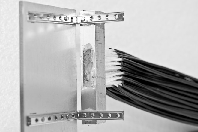
33. The new and improved fiber receptacle with its window shaped like the popup flash window.

34. I used a thin plastic sheet wrapped into a funnel (not actually shown here) around the fiber ends to put the whole thing through the flash window.
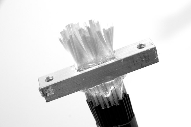
35. Then I epoxied the whole thing in place. I used Pattex Super Mix 5-minute epoxy for this. This stuff isn't as runny as some other epoxies. For some extra security, and because the epoxy didn't reach the spaces in between the tiny fibers, I applied a few drops of cyanoacrylate, aka superglue.
36. I used a dremel with a cutting wheel to trim the fibers. A knife wouldn't cut it; it's glass, after all. I polished the ends with a polishing wheel and polishing compound. It's not as clean as I would've liked, but the results are just as satifactory as with the large connector.
I also decided to improve the filter mount ring. I now own a couple of semi-pro lenses with 77 mm and 82 mm filter sizes (see my equipment page) and I wanted to be able to use those with the ring flash. I also made it substantially deeper so it gives me a bit more stability. It's basically a plastic tube glued onto a filter step-up ring.

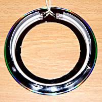
37. The improved lens mount.
Now, before I show you the new setup, for which I have to set up my studio lights and stuff, I can finally show some real world shots. The following 4 photos were done with a Kenko macro tube set (all 3) and the good old Minolta AF 135 mm f/2.8. Please note: I'm not used to doing macros (yet!) so bear with me. Once I'm up to speed, images will start getting better, and I will probably try to get higher magnifications. I might even decide to get a dedicated macro lens.

38. Ladybug. Bright sunlight, ring flash used as fill light only. 135 mm, f/11, ISO 200.

39. Spider. Shade, ring flash supplying most of the light, 135 mm f/8, ISO 320.

40. Bumblebee. Shade, ring flash supplying most of the light, 135 mm f/8, ISO 320.

41. Bumblebee. Shade, ring flash supplying most of the light, 135 mm f/8, ISO 320.
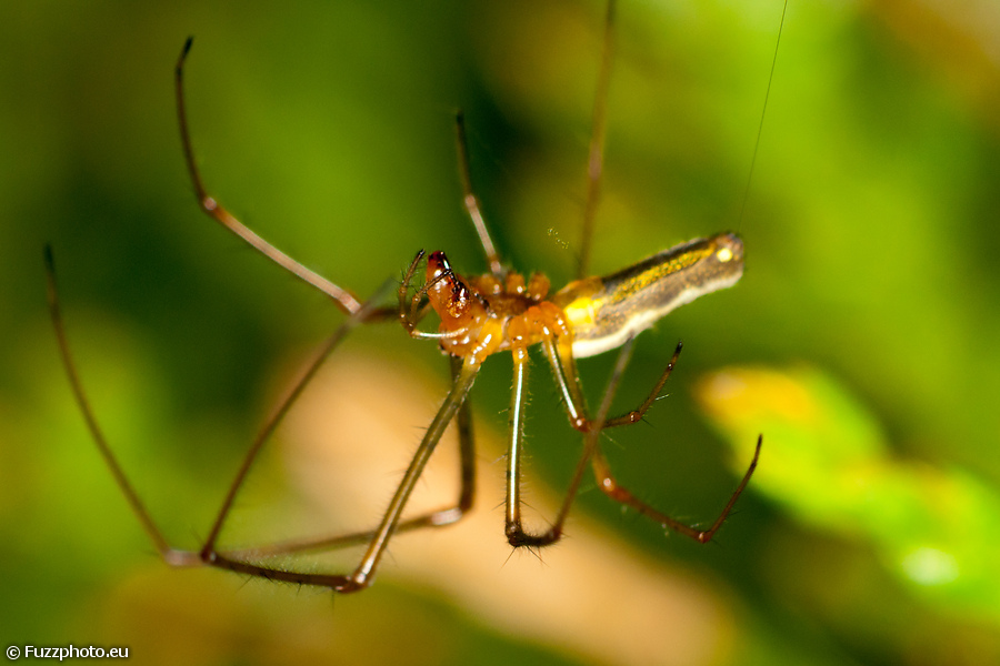
42. Stretch spider. Shade, ring flash supplying most of the light, 135 mm f/8, ISO 320.
Future plans
- Foam ring diffuser: I might lose too much light, but we'll see...
- Tube diffuser: imagine having a tube attached to the end of your lens, that lights up on the inside, wrapping the light around your macro subject completely...
- CCFL ring modeling light: I still have some leftover 80 mm CCFL rings. I could use one of those in this project as a focus aid and modeling light...
Cost
As usual, I'm concluding the article with a cost analysis. Most of the stuff comes from my many junk boxes. The bracket, plastic panels, rings, foam pad, etcetera. The only thing that was purchased specifically for this project is the fiber assembly, for the rediculous amount of € 10!
Fuzzcraft.com comment system 1.1
2011-09-11 Don
Cool! Good job! Love the ingenuity.
2011-11-21 Avinash Arora
Amazing work, as always! Long time follower, and finally got a DSLR worthy of attempting my own fiber ring flash. I think I'm going to try to modify an external flash diffuser to implement one. I'm excited!!!
2012-06-21 Billacat
All of your projects are truly inspirational. The attention to detail both in the product and the writeup is exemplary. Fuzzcraft, have you taken any people photos with the fiber optics macro setups? If so, please post.
2012-06-23 Admin
Unfortunately for you, I haven't. Simply because of the fact that I don't like the look of ring illumination on portraits. I have always intended these rings for macro work.
I don't do much of portrait work, and maybe I should - because it's fun - but there's some work on http://fuzzphoto.eu/#3,01 but none with ring lights.
2014-12-12 fatbeard
Great stuff!
I actually have at least one of those fibre assemblies lying around (bought on a whim) and was still wondering what to do with it...
Now I know: build one of these contraptions for my own (usually work-related) macro-photography: http://www.uploadarchief.net/files/download/fotocell%20001.jpg and http://www.uploadarchief.net/files/download/img_0578.jpg ...
No signing up, no censoring, no hassle, no strings attached, no nothing.
Please, English or Dutch only. If you don't really want your message to appear in public, consider contacting me privately.