 Photography
Propeller clock 2
When I built my first propeller clock, my intention was to use it as a normal clock for continuous use in the living room. But I was disappointed by the fact that the clock, despite all efforts, wasn't dead silent. All of the generated noise seemed to come from the sleeve bearing in the VCR capstan motor. I tried lubricating it with very thin mineral oil, but it was no use. I had to go back to the drawing table and design a dead silent propeller clock.
Well, I still had the VCR around somewhere. And VCRs have rotating head assemblies. They run dead silent. And they have a way of communicating between the stationary part and the moving part. There were only 2 problems to be overcome: how to run the motor stand-alone (which I haven't been able to yet, because I can't find anything on the AN8275N driver chip), and how to squeeze power through the rotary transformer instead of video head signals. Here is a picture of the disassembled VCR head assembly (warning: BIG picture). Reading the picture like a text page, you can see:
- Head drum with magnetic pickups removed
- Rotating part of the transformer with the PCB attached, partly done
- Stationary part of the transformer, attached to the motor base in which I cut 128 synchronisation slots
- Stationary part of the motor and its control circuit
- Axis lock nut
- Magnetic rotor
- Magnetic shield plate
Click thumbnails to zoom in. Click again to zoom out, or use cursor keys to walk through all images.

1. I had an acrylic disc specially laser cut for this clock. It's 22.5 cm diameter and it contains 2 rows of 7 leds and 3 mounting holes for the motor hub.
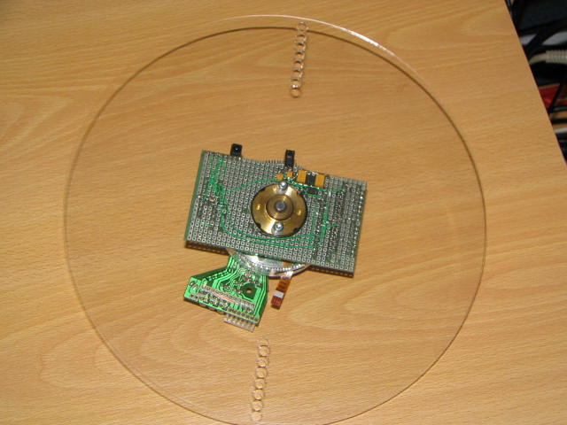
2. Each row of leds displays the same data at the same position, effectively doubling the refresh rate, or you could say the disc has to only spin at half the refresh speed. This helps reducing noise even further, as well as reduce power somewhat. The next 2 pictures show the hub, which has the secondary of the transformer and the circuit board attached (yes, those are surface mount components), mounted underneith the disc.

3. A closer look

4. I then reassembled the motor. You can clearly see the 128 slots I cut into the motor base and the light shaft to pick them up in order to synchronize the image.
The circuit is gonna be pretty straightforward. A base will contain a power oscillator to drive the primary of the transformer. The moving part consists of a PIC16F88 controlling 2 shift registers, which in turn drive 2 7-fold darlington NPN arrays. The led current is set to 80 mA. I will only drive them with very short pulses to increase the sharpness of the image. The remaining bit of each shift register is used to create a glow-like effect: all leds are fed with a very low continuous current (using the free wheeling diodes in the transistor arrays to separate the leds electrically). Power from the secondary will be rectified by a fast schottky diode, then buffered by tantalum caps, filtered, and regulated by an LM2940.
This project has not been finished, to date. I doubt it will ever be. Don't ask me for source files or a schematic. I only have non-working, non-finished stuff to show you. It wouldn't help you build this clock in any way.
Fuzzcraft.com comment system 1.1
No signing up, no censoring, no hassle, no strings attached, no nothing.
Please, English or Dutch only. If you don't really want your message to appear in public, consider contacting me privately.