 Photography
Professional projects at Dinaf Traffic Control
Contrary to the what the name says, Dinaf Traffic Control has nothing to do with controlling traffic. This small Dutch company was founded in 1976, and started out by importing traffic counters and traffic signal lamps, the latter led to the company name. Some years later, Dinaf started developing their own brand of traffic counters and quit selling signal lamps altogether. Today, it maintains a large network of traffic counters in the Netherlands, and provides all sorts of services in traffic counting for government bodies and companies. I worked there from 1997 to 2003 as an all-round technician, but came back in 2007. During that first period, I did some lightweight development work, which would officially become a part of the job in the second period. Below are some of the things I developed and helped develop.
Counting traffic
First, a short explanation of how traffic is counted. For temporary sites, mostly rubber tubes are used. The tubes are made of natural rubber for longevity, and are 13 mm outside diameter and 6.5 mm inside diameter. The tubes span across the road and are fixed with metal clamps and special nails on the sides. For simple counting, one tube per traffic lane is needed. The tube is overrun by a vehicle tyre, air is compressed inside it, and at the end, an air pulse comes out. A microphone-like device detects the sudden change in pressure and puts out an electrical pulse. The counter module of the counter system simply counts all pulses and stores them each 5, 15, 30 or 60 minutes or 24 hours.
For speed and length measurement, two tubes per lane are used, spaced 1 meter apart. From the time delay between the consecutive pulses, speed and axle distance can be calculated. The measurements are stored in classes, ie. all vehicles with speeds between for instance 30-39 km/h are counted separately. The same goes for 40-49 km/h, 50-59 km/h etc. Axle distance is also measured, and classified in the same manner. A device that counts traffic in this manner is hence called a classifier.
For long term sites, induction loops are used. Thin rectangular cuts are made into the road, and 4 loops of heavy duty wire are put into them. A counter or classifier with loop detectors is then installed on a 5 ft. pole at the side of the road. The detectors make the loops resonate at a frequency of about 40 kHz. When a large metal object passes over the loop, its frequency changes slightly and the detector signals the counter that a vehicle is passing.
New counter system
Around 2014-2015 I started drawing up the specs for a totally new core for our traffic counters. The current system was designed in 1986, and revised in 1990 and 1994, but has evolved very very little since then. Technology has - significantly. A number of components used in the current system are near obsoletion. Instead of trying to improve an old, aged system, a choice was made to start from the ground up. The hardware specifications are as follows: an extremely low power, high pin count, 16-bit microcontroller with an on-chip USB host for control and readout via mass storage devices, a relatively large amount of storage on internal flash memory, and the possibility of an on-board cellular engine for wireless access. Most of the new system features will be embedded in firmware. Storage of data will be on a per-vehicle basis, and support for remote readout and live traffic monitoring will come standard. At the moment I'm building a hardware prototype. When that's done, I will probably spend a year, on and off, developing the firmware.
Bluetooth stick
As a direct result of the increase in portable computing (tablets, smartphones) I developed a small Bluetooth 2.0 dongle in 2014. It allows an Android or notebook user to control our counters using Bluetooth and a free terminal application. Unfortunately, due to Apple's decision to cripple iOS devices' Bluetooth capabilities, it won't ever work on an iPad or iPhone.

1. The Stick simply plugs into the front communications port of the counter.
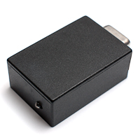
2. The other side sports a super bright blue status LED.
Presentation
In 2010 I built a graphical presentation on a 42" HD monitor, to be used in the company building's entrance hall, and to draw the attention of visitors on the Intertraffic convention in Amsterdam. It's available online at the Dinaf website. It's in Dutch, of course, and you need a viewscreen with at least 1920x1080 pixels to fully enjoy it.
Software
I built a small application running AWK scripts, and as such it can be seen as a file converter. Customers who partly work with a competing brand of traffic counters can now import their data into our data processing and database software. The application has also come in very handy to very quickly assess a count on-site. We do this at every single site we stop by, and the new app can save up to 30 minutes of work a day, compared to the ancient DOS application we have been using for over 10 years, for lack of something substantially better. It has also come in very handy for various corrections on counter data files.
Rampack reader
Ready just in time for spotlight duty at the 2010 Intertraffic convention, I finished the design and prototypes for a new Rampack reader. Our current line of counters output their data into a module that contains up to 256 kB RAM memory and a battery. Old fashioned, but that's the way it is. The device that read these Rampacks into a PC was time consuming to build, rather large, very slow, required separate grid power, and utilized a serial port. The newer design connects directly to USB, doesn't need separate power, and is 10 times as fast (with an option to increase that to 50-fold), and about 10 times as compact. It is also considerably more intelligent, being able to test the Rampack's battery and data validity, and signalling any sign of trouble with a status LED. It can even correct for simple errors like a missing protocol identifier!

1. The printed circuit board. It contains a PIC16F887 and a FTDI232R as its main ingredients.
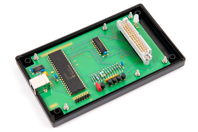
2. PCB fitted into the lower part of its enclosure.

3. The prototype with its paper front.

4. The actual production model.
GSM cellular modems
In order to remotely access traffic counter data, a cellular modem can be installed. Powered by a 6 Volts, 10-20 Watts solar panel and two or three 6 Volts / 12 Ah lead acid batteries, it can be left unattended virtually forever. A software package, specifically developed for Dinaf, can be instructed to call a list of counter sites, retreive all data and start a new count. Sites may be equipped with a standard V22 line modem (for plain old telephone service) or a GSM. Different script files allow different site setups to be read out.
I developed 5 different cellular modems over the years. Starting in 1998, the first two were external ones. I hacked a commercial cellular modem into taking a lower supply voltage, and reduced the power consumption down to an impressive 80 mW. It was labour intensive, though. I did about one hundred of them but in 2002 took a different approach, moving the modem to the counter rack as an internal module, the GSM-3:
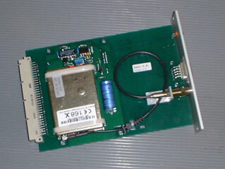
Communication speed is fixed at 4800 baud. The microcontroller in the counter system can't reliably send data at 9600 baud. A flashing LED indicates registration status and call-in-progress. A nasty problem arose with these modems in the field. After being registered to the network for some time, some modules (especially the ones in crowded areas) failed to stay registered. Sometimes this manifested itself after as long as a month, but eventually it would be thrown off the network every time. I designed an external add-on box containing a microcontroller to force the modems to stay registered. This setup worked beautifully for many years, but the cellular engine became obsolete and was having trouble with high supply voltages, so the natural successor was, of course, the GSM-4, introduced in April, 2009:
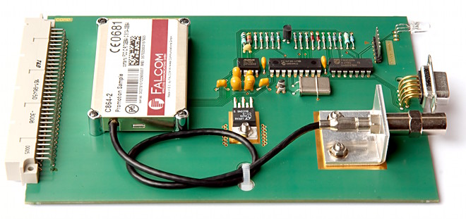
I redid the existing design to fit a newer cellular engine and joined the external add-on module onto the modem circuit board, along with a powerful voltage regulator. The modem is now completely plug-and-play, and doesn't require any setup or adjustment, and is forced to stay registered to the network. It monitors its own power supply voltage and reception strength, and keeps a log of that, which can be accessed remotely. The (now bicolor) LED indicates power status, registration status, reception and call-in-progress. The heart of the board consists of a Microchip PIC16F88, and the firmware is about 2,100 lines of assembler. Plans to let it send a text message when power supply is below a certain level are on the drawing board. And to top it all off, the GSM-4 requires only one third of the power of its predecessors, and consumes as little as 25 mW.
WM-5
Then 2012 came, and once again, the cellular engine had become obsolete. Generation 5, dubbed WM-5, takes the exact same approach as the GSM-4: an internal rack board with a data connector and an antenna jack. This time employing a SIMCom SIM900BE module, reducing power consumption to a staggering 10 mW. I kept the PIC16F88 microcontroller, but added hardware and firmware to include 2.5G (SMS, direct TCP/IP access and e-mail), and periodical checks of the counter itself. In case of a failed check, the modem will send an SMS message and/or e-mail report. The modem will also be able to reset the counter remotely in case of a disaster. The latest firmware adds automatic, timed e-mail readouts, and SMS triggered e-mail readouts. All in the tiny amount of flash available in the PIC16F88.

Website
In September, 2007, right after returning to Dinaf (after having worked for a different company for a few years), I built a new Dinaf Traffic Control corporate website. It was a complete redesign, leaving literally nothing intact. The old website was not only designed very inefficiently, it was also not search engine optimized (not even slightly), it didn't conform to any known standard (not even slightly) and it didn't supply a shred of information about Dinaf's main activities, which have shifted considerably over the years. It was time for a change. I had been honing my skills at building static websites for a few years (see the changelog of this website), so it was time to put them to the test and see if I could do a professional site. With my experience in photography I was able to pull off some convincing product photography as well. In the years to follow, numerous updates were done, mostly without delay and correcting errors often the same day.
Tube counter tester
This is a test machine I built to replace an aquarium pump that generated 25 Hz air pulses and could only connect two tubes. I thought at least to double that amount and to add actual vehicle simulation. For this to work I needed a microcontroller. Having gained experience with the FC-50 foot pedal, I of course used the same chip (PIC16F84-04P) for this project. And what a nice project it turned out. Upon power-up, it recalls its settings from permanent memory and starts simulating traffic on 2 lanes. To change the settings, one can connect a terminal (same one as the ones used for the traffic counters themselves) and change speed, length, number of axles and intervals of each lane, and store them in memory if required.
Being a speaker designer, I considered small loudspeakers to be a good method to generate air pulses. In the picture above you can see 4 Visaton FRS-5 loudspeakers connected to tube connectors. Two of the connectors in the picture have tubes on them. It simply puts 12 volts on the speaker for a very short period of time (0.01 seconds) and the speaker pops out an air pulse. One of the counter's air pressure sensors picks up the pulse as if it came from a tube over a road being depressed by a car tyre. When no tubes are attached, the air pulses can be clearly felt a few inches away from the connectors.
Dinaf now employs three of these testers, and they're in use very regularly.
Loop counter tester
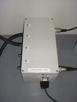
Much like the tube tester, I made a loop classifier tester. Loops are a different way to detect traffic. A rectangular inductor (a loop) of 1.5 by 1.8 meters with 4 turns of heavy wire is embedded in the road surface. A socalled "detector" unit in the traffic counter puts a frequency of around 40 kHz on the coil. When a vehicles passes over, this frequency changes and the detector puts out a signal to the actual counter.
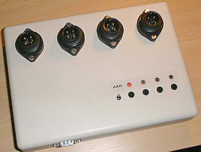
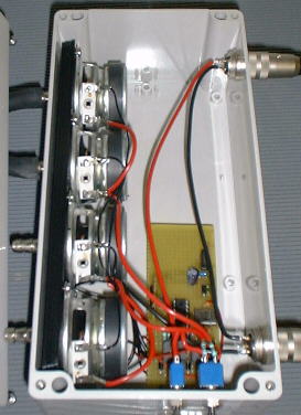
This tester simulates traffic on 4 lanes with different speeds and vehicle lengths. It has 4 preset buttons which call up different settings. A terminal can be connected to change every setting in every preset and presets can be stored and copied to other presets. Loops are simulated by switching small ferrite core inductors. Inside is a PIC16LF628-04I/P running at 3.6864 MHz.
Calibration machine
This one-off piece of equipment is used to speed calibrate every single traffic classifier sold. It's made from an old daisy-wheel printer. All electronics, the paper transport system and the head were removed. Horizontal movement is controlled by a large DC servo with a quadrature encoder on its rear axle. The carriage is attached to a geared belt. The electronics let the motor synchronize with a crystal-based frequency, this way a very constant speed of the carriage is obtained. The carriage has a ferrous metal plate attached which passes along two 2" coils, simulating a vehicle passing over detection loops.
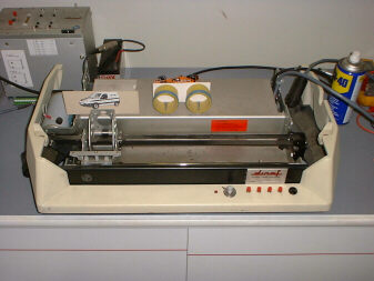
4 preset speeds can be selected. The carriage moves back and forth automatically, waiting for a few seconds every time it returns to its starting position. This project does not utilize a microcontroller. It is built with about 15 standard CMOS logic ICs.
After about ten years of use, the main DC servo was completely worn out, which rendered it useless. In 2014 I rebuilt it, replacing the servo with a stepper motor, replacing the CMOS logic board with a microcontroller for more accurate speed control, and a more realistic setup of the loops (a scaled down representation of a piece of road).
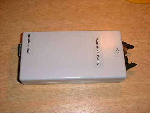
Matrix sign
This small unit can be connected to a traffic counter with loop detectors. It separately determines the speeds on 4 lanes of traffic, and puts out a signal on either or both of its 2 outputs when a vehicle is speeding. A socalled matrix sign (with a text along the lines of "You're speeding") is then switched on for a few seconds.
Speed limits, response times and calibration values can be programmed for each of the 4 incoming lanes through the serial terminal, that's normally used for the traffic counter itself.
The cost savings for our customers are quite large. Almost everything is already on-site: detection loops, detectors and power. Only this small module and the sign have to be installed. Future enhancements include a wireless connection between controller and sign, and on/off switching by modem.
Inside view: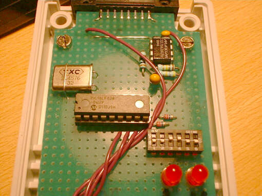
The matrix sign controller is built around a PIC16LF628, the same as used in the GSM-3 control add-on.
This is what the 60 by 100 cm sign looks like: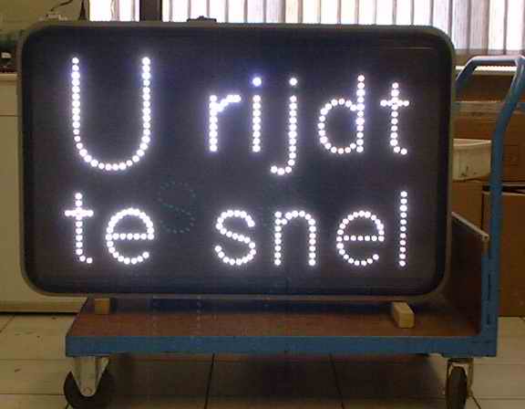
This project never made it into a real product, and we only installed a number of prototypes. The pre-installed electronics in the signs were unreliable (the counter module was not), the radio link was too intermittent in crowded areas and it did not generate a lot of interest for government bodies.
Fuzzcraft.com comment system 1.1
No signing up, no censoring, no hassle, no strings attached, no nothing.
Please, English or Dutch only. If you don't really want your message to appear in public, consider contacting me privately.