 Photography
Ring light 1.0: 30 LED ring light
Note from the author: my ring light pages have had hundreds of thousands of visits since I started writing them back in 2005. Fuzzcraft has been stampeded by StumbleUpon, has starred on Hackaday and DIYphotography, and is constantly being linked to from flickr, strobist and other blogs, forums, etc. I thank you all. It's nice to have done something that appeals to so many people.
There's something magical about ringlights. The unnatural light cast, the halo shadows. Yet the idea behind them is as clever as it is simple: looking through the light source.
Overview
Want to see more ring lights? See my full ring light overview page
Quick overview:
  |
4.1 |
Fiber optic TTL flash ring light, uses popup flash and 67 fiberglass bundles |
  |
4.0 |
Fiber optic TTL flash ring light, uses popup flash and 120 plastic fibers |
  |
3.1 |
2 CCFL continuous ring light |
  |
3.0 |
4 CCFL continuous ring light |
  |
2.1 |
52 mm filter mount 140 LED continuous ring light |
  |
2.0 |
52 mm filter mount 90 LED continuous ring light |
  |
1.0 |
Simple, 30 LED continuous ring light |
This project sparked my interest to build a ring light for close-up photography. The advantages of a light source that surrounds the lens are obvious: no shadows will be cast on the subject, making it appear almost evenly lit. Using LEDs for this task also has some advantages over flash light: because the subject is being lighted continuously, both white balancing and light metering work much better, resulting in much better color, and no try-out shoots. Here's how I did it:
Click thumbnails to zoom in. Click again to zoom out, or use cursor keys to walk through all images.

1. In a recent LED sell I purchased around 2000 various LEDs, including 100 white ones.

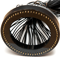
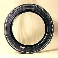
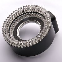
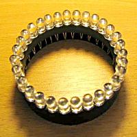
2. Using my trustworthy, cheap rotary tool, I cut 2 rings from a piece of 60 mm (outside diameter) PVC tube. A narrow one of about 6 mm (below) and a wider one of about 17 mm.

3. A small part from the narrow ring was cut out to be able to compress into the wide one, locking the LEDs in place.

4. The result: a bunch of leds held firmly together by 2 plastic rings. The 30 leds are connected as 3 strings of 10 leds.
That was the construction part.
Power supply
Next was the power supply. I decided on 25 mA per led, giving maximum light output while not stressing anything. I wanted the ring to be powered by 4 (older) NiMH batteries or a wall socket power supply. I always try to keep things as universal as possible. The most obvious scheme is to put all 30 leds in parallel, each with their own current limiting resistor. This approach has 3 drawbacks:
- At least 33% of the power is wasted in heat, and those watts have to go somewhere
- I won't be able to use another input voltage without an additional regulator, meaning more heat
- Every single LED requires its own current limiting resistor
- Brightness varies a lot with battery clamp voltage.
To solve all three problems at once, I used an LT1170 step-up switcher with current feedback (an LT1172 would have sufficed, but I had none lying around). The LT1170 boosts the voltage to about 35 volts. Each LED string has a 50 ohms resistor. The current is sensed on one of these. The regulator has an internal reference of 1.23 volts, so 50 ohms results in a led current of almost 25 mA. Unfortunately, only one string of 10 LEDs will be precisely at this current. Differences between single LEDs will influence the currents through the other 2 strings. Without a lot of additional electronics, this can't be undone, so I chose to leave it this way.

5. Here's the converter. The photo is taken with the ringlight switched on for the first time. I held it around the lens barrel with one hand, and took the picture with the other. I did manage to do a white balance correction, and I think the colors are quite good. Please, no commenting on my soldering. It's messy as hell, but it does work! The 470 uH coil is on the back of the PCB. The LEDs are not aimed correctly yet, as you can see by the darker center of the picture.

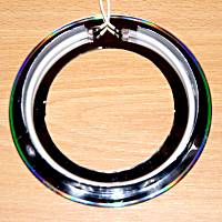
6. Switched on, back side.
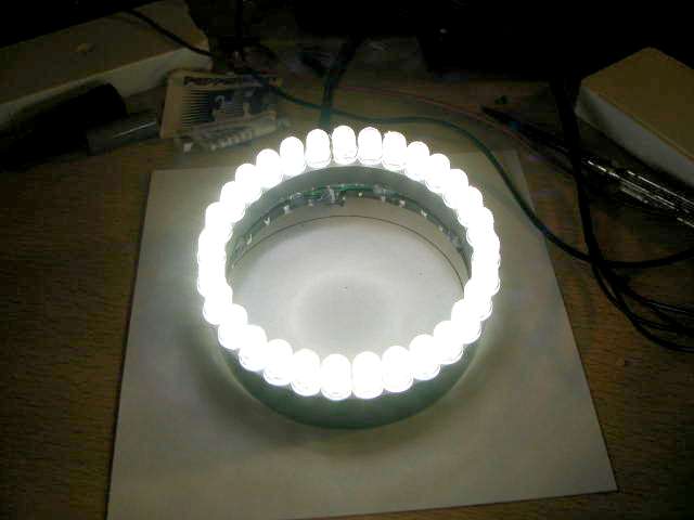
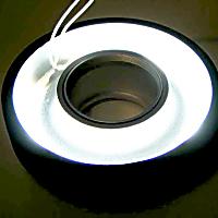
7. Switched on, front
The converter efficiency turned out somewhat of a disappointment. With an input voltage of 5 volts, current draw was 600 mA, the output was 32.78 volts at 76 mA. 3 Watts input, 2.5 Watts output gives 83%. This might need improvement, but I guess it's not really that bad. I also should provide some means of protection, because when an open circuit occurs in the current-sensed LED string, the other LEDs will be scorched. That LT1170 could push a car out of its way, if it had to.

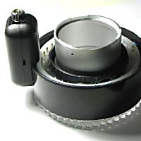
8. The converter was fitted into a very small soapbar case. Here, everything's hooked up.

9. I attached the ring to the camera by an aluminium strip connected to the tripod mount (please don't mind the blurry picture, it's shot with my 1999 Fujifilm DX-10).

10. Here are two example pictures. The first one is take with a small desk lamp.

11. The second one is taken with the ring over the lens.

12. Now, maybe the neatest part of all, the whole thing fits into a flashlight case I had lying around. This is pure coincidence. I swear!
Last but not least, here's the schematic for the converter and the LEDs:
Continue reading about ring lights: Ring light 2.0
Fuzzcraft.com comment system 1.1
No signing up, no censoring, no hassle, no strings attached, no nothing.
Please, English or Dutch only. If you don't really want your message to appear in public, consider contacting me privately.