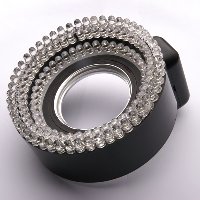
Ring light 2.1: 140 LED ring light
Note from the author: my ring light pages have had hundreds of thousands of visits since I started writing them back in 2005. Fuzzcraft has been stampeded by StumbleUpon, has starred on Hackaday and DIYphotography, and is constantly being linked to from flickr, strobist and other blogs, forums, etc. I thank you all. It's nice to have done something that appeals to so many people.
There's something magical about ringlights. The unnatural light cast, the halo shadows. Yet the idea behind them is as clever as it is simple: looking through the light source.
Overview
Want to see more ring lights? See my full ring light overview page
Quick overview:
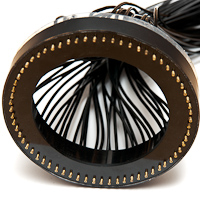
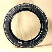
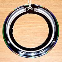
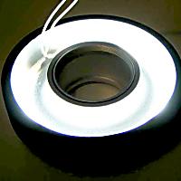
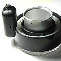
About a year after I built ring light 2.0, I upgraded to a digital SLR camera. The ring had to be modified to fit my Sigma 70-300 f/4-5.6 APO DG macro lens. Fortunately, the inside of the LED ring is wide enough for the relatively small barrel of said lens. Still, some parts had to be repositioned to make the front thread of the lens reach the thread of the filter frame embedded into the LED ring.
One huge drawback of this whole thing is the fact that the extended part of the 70-300's lens barrel rotates when focus is adjusted. The Dynax 5D is more than capable of moving the whole thing with its autofocus motor, but even then it's inconvenient to have such a large part of your setup move around, especially if there's a power cable attached to that moving part. That's why I did something that earns me a pat on the back: I trashed a cheap polarising filter. This filter has a rotating front rim, and attaching the ring light onto it makes the lens barrel rotate independently of the ring light!
Click thumbnails to zoom in. Click again to zoom out, or use cursor keys to walk through all images.
More LEDs
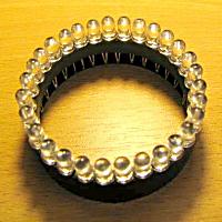
The second upgrade was in the number of leds. I was happy to report that my ring light 2.0 had 2 rows of LEDs; version 2.1 features a third row! This makes for a total of 140 white LEDs. Many photographers can confirm that there's no such thing as too much light. Not that this ring is a match for a ring flash. White LEDs can be had for about $0.20 by the 100, so in case you thought I spent a fortune on LEDs, guess again. Unfortunately, after installing the third LED ring, I found out the last batch of LEDs had some bad ones, and I had to open it up and replace them. So, you might wanna check the individual LEDs for equal output.
By the way, for a more thorough description of the power supply and my motivation to use such a complicated setup, please refer to the Ring light 1.0 and Ring light 2.0 projects.
Tests
7. 2nd test shot. This time I employed one of my +1.6 diopter achromats. Bright white object, 135 mm f/6.3 1/60s ISO400
At this time an interesting phenomenon became visible: while the LEDs were heating up, the LT1170, being purely current fed back, started turning down its output voltage. An explanation for this is beyond the scope of this document, but it boils down to the following: the forward voltage of a diode drops slightly when the temperature of the P-N layer rises. Because I have 10 LEDs in series in each of the 14 strings, the effect is clearly visible. The LT1170 is a switching regulator, so when output voltage drops and current is constant, the input power decreases when the LEDs heat up.
Specifications
| Preliminary specifications | ||
| Dimensions | Outer diameter Depth Converter part Mount |
105 mm 43 mm protruding 10 mm outside diameter and 45 mm towards camera, including angled power connector 52 x 0.75 filter thread |
| Electrical | Input voltage Input current Converter output Converter efficiency Power connector |
7.2-25 V, 15 V nominal 930 mA at 15 V 32 V, 375 mA 85% at 15 V input DC plug 5.5 x 2.1 mm |
| Optical | Color temperature Light output Exposure value |
appx. 9,500 K appx. 300 Lumens Undetermined |
I would rather have made this ring light fit my Sigma 17-70 f/2.8-4.5 DC, but the front element of this lens is just too wide and it would mean starting all over again. So instead I reworked the failed CCFL ringlight (V3.0) project for the 17-70 lens, which is much better at focusing really close anyway (2 cm from the front element at 70 mm), so the scattering of the light, which proved V3.0's major drawback, might actually be a benefit. Read about it here.
The schematic:
Some additional words about the schematic: you don't have to use a step-up converter. If you think it's too involving, just use any configuration to supply the LEDs. Still, you might want to get a supply voltage as high as possible (which is tough, with batteries) to avoid having to put a series resistor with each LED. This is not only a lot of extra work, but those resistors have to go someplace, and they generate heat. The LEDs are heating up quite a bit as they are, so you might want to rethink that scenario. Whomever told you that LEDs don't heat up is a moron. And don't even think about putting 140 LEDs in parallel, if you value evenly distributed brightness.
 Photography








Fuzzcraft.com comment system 1.1
2013-06-25 Ninad
I really like this design. It seems to work fine and is easy enough to make. I have one question though. I plan to use it on a 50mm prime. My question is: Won't there be any spillage of light from the LEDs directly onto the lens? Since LEDs emit light in all directions, won't some of it fall directly on the lens and cause flare or distortion?
Hope you reply soon.
Thanks in advance.
No signing up, no censoring, no hassle, no strings attached, no nothing.
Please, English or Dutch only. If you don't really want your message to appear in public, consider contacting me privately.